Composite model
Note
Time required: ~15 min.
In quick start, we fitted a 2D ring to single nuclear pore complexes (NPCs). However, in 3D, there are actually two parallel rings per NPC (which can be seen in the side view). To extract parameters such as the distance between the two rings, a different geometry is required. Normally, this would require the user to create a new file with some coding. However, this particular geometry can be derived from the existing one (i.e., twice the 2D ring in 3D). Building a composite model by combining existing ones without coding is supported by LocMoFit.
Task
Building a composite model with the GUI. We will build a 3D dual-ring model by combining two times the identical ring model ring3D.
Requirement
Software: SMAP installed. Further information can be found on our GitHub site.
Localization data: U2OS_Nup96_BG-AF647_demo_sml.mat
Fitting settings:
dualRing_model1_fitPar.csv
The data and setting files can be downloaded here.
Main tutorial
Preparation
Start SMAP (how to?).
Important
If you continue from the previous tutorial, please close the current SMAP and start a new session.
Load the dataset U2OS_Nup96_BG-AF647_demo_sml.mat. (how to?)
Go to [ROIs] -> [Settings], click show ROI manager. This opens the ROIManager in a new window.
Load the plugin LocMoFitGUI in [ROIs] -> [Evaluate] (see quick start if you forget how to do it).
Setup
We will combine two identical rings in 3D (ring3D) to form a 3D dual-ring model.
We first load the individual models and set up the arguments of the model parameters. Now for the first ring model:
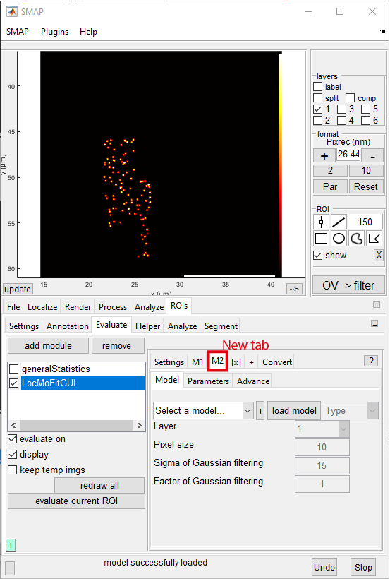
Go to [M1] -> [Model], click the drop-down menu (where select the model… is shown), and then select ring3D. Click load model.
Go to the tab [Parameters] and click the button Import. In the new window, navigate to the settings directory and open dualRing_model1_fitPar.csv. Another new window should show up:
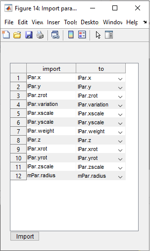
Click Import button in the popup window. Now the parameter arguments/settings are updated.
Note
In the new window, the saved parameters (the field import) are matched to the parameters (the field to) in the GUI based on the same names and model types. We will discuss this more in step 2.
Hint
Now you loaded a previously exported parameter settings. In LocMoFit, you don’t have to manually input the parameters every time. You can save the current settings through the Export button and use them for the next time.
Now you have to tell LocMoFit that we need to add a second model:
To add the second model tab [M2], click [+] next to [[x]]:
You are now in [M2] -> [Model]. Click the drop-down menu (where select the model… is shown), select ring3D, and then click load model.
Go to the tab [Parameters] and set all fix to true except for the parameter z. Next, change the value of weight to 1. Also change the value, lb, and ub of z to 40, -40, and 60. Now the table should look like this (non-default values are in bold):
name
value
fix
lb
ub
type
min
max
x
0
☑
-150
150
lPar
-150
150
y
0
☑
-150
150
lPar
-150
150
zrot
0
☑
-Inf
Inf
lPar
-Inf
Inf
variation
0
☑
0
10
lPar
0
20
xscale
1
☑
1
1
lPar
1
1
yscale
1
☑
1
1
lPar
1
1
weight
1
☑
1.0000e-05
1
lPar
1.0000e-05
1
z
40
☐
-40
60
lPar
-300
300
xrot
0
☑
-Inf
Inf
lPar
-Inf
Inf
yrot
0
☑
-Inf
Inf
lPar
-Inf
Inf
zscale
1
☑
1
1
lPar
1
1
radius
53.7000
☑
0
0
mPar
0
100
Important
Why are there so many zero values? Zeros mean that those parameters share the same values as M1. When there is more than one model, the extrinsic parameters (lPar) are always defined relative to the M1. For example, we set the value of z of M2 to 40 nm in order to move it 40 nm away from M1 in z, having the two rings separate.
To have better starting parameters, you may not want to always set the xy positions to zero. Instead, they can be roughly estimated based on the median position of the localizations. To take the median values as the starting parameters, you can use the functionality Convert, which dynamically converts from a Rule to the starting value of a parameter specified in Target_fit.
Go to tab [Convert] and fill in the table as the following (you can use the + button to add a new row):
Source
Rule
Target_fit
Target_usr
this step
median(locs.xnm)
m1.lPar.x
this step
median(locs.ynm)
m1.lPar.y
this step
median(locs.znm)-40
m1.lPar.z
Note
Here we assign the median (xnm, ynm, and znm refer to the values on the respective coordinate axis, in nanometer) position of localizations (locs) as the initial parameters for the center position of model 1 (e.g., m1.lPar.x means the x position of model 1). Model 1 is additionally shifted 40 nm down in z.
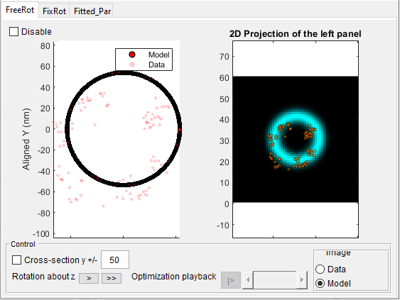
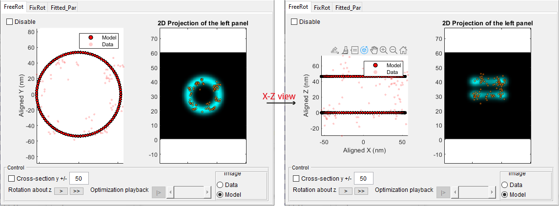
Now preview the model before fitting for site 1 (see quick start if you forget how to do it). The expected result:
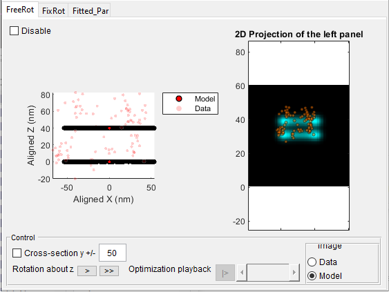
Tip
In the viewer, how do I explore the model in 3D? In the scatter plot on the left, you can either hold the left-click and drag or right-click and select views:
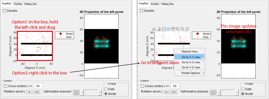
Go to X-Y view, you will see the side view of the model:
Fitting
To disable the preview mode, uncheck preview in the tab [Parameters].
In the ROI Manager window, click on one site and wait for a few seconds. You should see the updated LocMoFitGUI window displaying the fitted model:
Note
To see the effect of fitting, you can compare the model before and after fitting with/without the preview mode on.
Saving all settings
You can save the current settings, including the loaded models, parameter settings, and converter, for the same task next time:
Go to [Settings], click on the button save, navigate to where you want to save the settings, and save it as NPC3D_step1_dualRings_LocMoFit.mat:
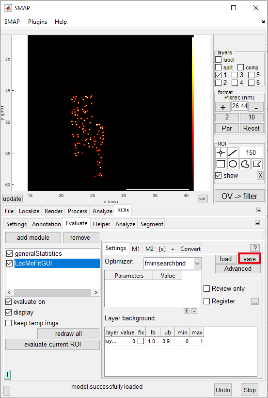
Congratulations! Now you retained the settings of the composite model you built for the first time.
Next tutorial
You are in the introductory series. The next tutorial is Chaining steps